
We need to connect one CE pin per slave (or peripheral devices) in our circuit. This pin is used to receive data from a slave to the master. MISO: It stands for Master In Slave Out.This pin is used to send data from the master to a slave. MOSI: It stands for Master Out Slave In.GND: Connect all GND pins from all the slave components and the Raspberry Pi 3 board together.5 pins are needed for the SPI communication: If the SPI device needs to communicate back to Raspberry Pi, then it will send data back using the MISO (Master In Slave Out) pin. Data is synchronized using a clock ( SCLK at GPIO11) from the master (RPi) and the data is sent from the Pi to our SPI device using the MOSI (Master Out Slave In) pin. It is used by the Raspberry pi board to quickly communicate between one or more peripheral devices. SPI (Serial Peripheral Interface) is another protocol used for master-slave communication. Hardware PWM is available on these pins only: GPIO12, GPIO13, GPIO18, GPIO19.Some specific pins are: PWM (pulse-width modulation) Pins on Model 3B+ : When this pin is set to HIGH, the voltage at the output is 3.3V and when set to LOW, the output voltage is 0V.Īlong with the simple function of input and output pins, the GPIO pins can also perform a variety of specific functions. Note: Do not connect a device with an input voltage above 3.3V to any of the GPIO pins, or else it will fry the Raspberry Pi.Ī GPIO pin set as an output pin sends the voltage signal as high (3.3V) or low (0V).

Any voltage between 1.8V and 3.3V is read as HIGH and voltage lower than 1.8V as LOW by the Raspberry Pi. Input/Outputs pins:Ī GPIO pin set as Input reads the signal received by the Raspberry Pi, sent by the device connected to this pin. All the voltages are measured with respect to the GND voltage. GND: Ground is commonly referred to as GND. This pin can use to power up the Raspberry Pi, and it can also use to power up other 5v devices.ģ.3V : The 3v pin is used to provide a stable 3.3v supply to external components and also to test LEDs. The model B+ board consists of two 5V pins, two 3V3 pins, and 9 Ground pins (0V), which are unconfigurable.ĥV: The 5v pins are used to directly deliver the 5v supply coming from the mains adaptor. As these pins don’t have a specific function, they can be customized using the software.

A standard interface for connecting a single-board computer or microprocessor to other devices is through General-Purpose Input/Output (GPIO) pins. Like the previous model, model B+ also consists of a 40-pin GPIO. GPIO stands for General Purpose Input Output pins these pins are used to connect the Raspberry pi board to external input/output devices. The status LEDs on the board now only contain red and green colors and are relocated to the opposite end of the board. Other Changes: The B+ version also comes with other improvements like the SD memory slot being replaced by a micro SD memory card slot (works similar to the previous version). PoE: B+ model comes with a facility of Power over Ethernet (PoE) a new feature added in this device which allows us to power the board using the ethernet cables. USB Hard Drive: The board is capable of using an external USB hard drive.

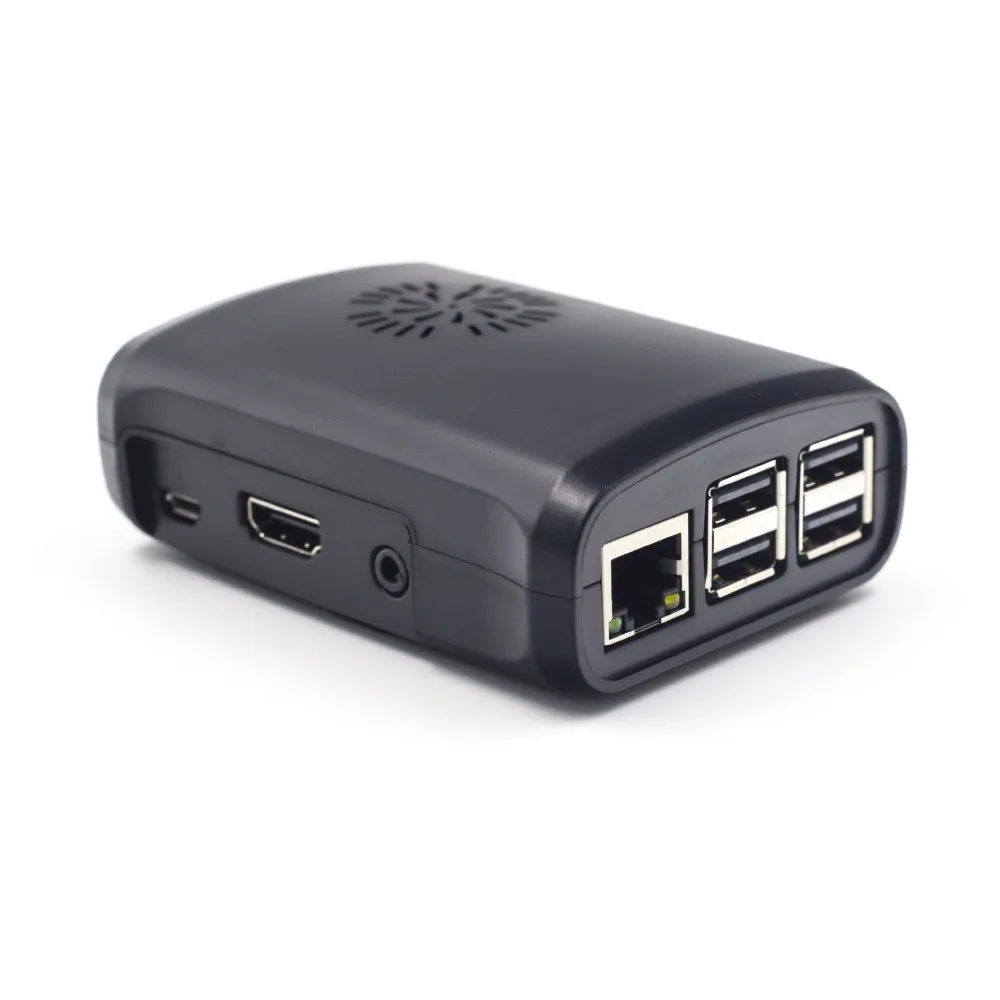
HDMI and Composite Connection: Both the audio output socket and the video composite socket reside in a single 4-pole 3.5mm socket which is placed near the HDMI port, and now all the power and audio-video composite socket are placed on the one side of the board which gives it a clean and nice look. The power connector is also repositioned in the new B+ model and placed next to the HDMI socket. Micro USB Power Source Connector: This connector is used for delivering 5V power to the board. Thus removing the hassle of connecting the USB hub in order to increase the ports. USB Ports: Similar to model B, model B+ also consists of 4 USB ports. It can provide up to 1Gpixel/s, 1.5Gtexel/s, or 24 GFLOPs of a general-purpose computer. The GPU uses OpenGL ES version 2.0, hardware-accelerated OpenVG API, and 1080p30 H.264 high-profile decode. GPU: It stands for graphics processing unit and is used for performing out the image calculation. RAM: RAM used in R-Pi 3 B+ is 1GB LPDDR2 SDRAM (similar to the previous version) BCM2837B0 is a 1.4GHz 64bit ARM quad-core Cortex A53 processor. Processor: The BCM2837B0 processor is the main component of this tiny board that helps in carrying out a large set of instructions based on mathematical and logical formulas.


 0 kommentar(er)
